Advantages
- New energy saving rotor to improve the hydraulic circulation and pulping efficiency
- Clearance between screen plate and rotor can be conveniently adjusted as required
- Belt drive or reducer drive are optional according to work space on site
- Single set or two sets parallel are both permitted
Structure and Principle
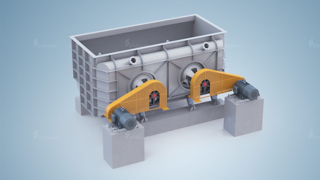
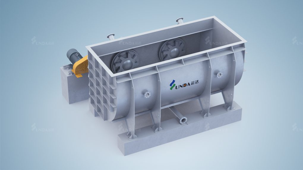
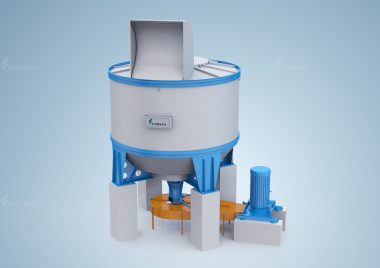
Broke Pulper is mainly composed of rotor and transmission part, etc.
The rotor is installed horizontally. When rotating, the water flow is sucked along the axis to the center and then flung out to surrounding, water circulation thus formed. By rotor shredding and internal friction generated by turbulence between layers with different flow velocity, the material is pulped and defibered under wet condition. The remaining paper and flakes will be further defibered between the rotor and screen plate. Wet paper and dry paper go into the pulp chest from the inlet on the top side. Well defibered pulp flow out the pulper through screen plate under force of water flow as the impeller rotates. Special design of pulping blades allows no plug of screen holes.
Pulp chest has transmission part at its end, consisting of main shaft, bearing housing and refined pulp chest, etc. Under the rotor is screen plate. Screen plates of different hole sizes are available. Clearance between rotor and screen plate is adjustable, normally 1-2 mm.
Technical Parameter
| Model | ZDSS23 | ZDSS24 | ZDSS25 | ZDSS26 |
| Nominal Volume (m3) | 5 | 10 | 15 | 20 |
| Consistency (%) | 3-5 | |||
| Capacity (T/D) | 30-60 | 80-120 | 120-180 | 180-300 |
| Motor Power (kW) | 75 | 110 | 160 | 185 |

